I have sending out between ten to fifteen resumes a week, reporting to the unemployment office, and going to school full time.
I have been using my saving for this project to keep our bills paid, and a roof over our heads.
This project is my only salvation to vent frustrations and keep my sanity.
To help with financially supplementing this project for materials needed to continue the restoration work, I have been selling off plastic model kits I have been collecting for over forty years.
Before I started to get into sanding the fuselage, that old coax for the antennae was really bothering me.

If you recall from an earlier post, this photo shows that the coax was replaced with a heavy ribbed one, and the old coax (White wire seen behind the copper tube) was left in the fuselage. Can we say extra weight!

I also discovered that when the new coax was installed, the person doing the work, drilled a hole straight through the fuselage side, and never repaired the damage. By the way, this hole is lined up with a second hole that the zip-tie was threaded through to hold the coax in place.
Well, I decided to put my IT networking experience to work. I'm going to replace that coax with the proper TSO'd aviation grade coax.
First, I removed the replacement ribbed coax, which wasn't difficult, since it was fished through only a couple of the original drilled holes and then tied in place with a plastic zip-tie (seen in top photo with a red circle drawn around it) in one place to then flop loosely to the antenna baluns in the vertical stabilizer.
The tricky part was removing the old original coax, which was broken off about arms length into the fuselage, and pulled into the vertical stabilizer.
I was able to fish the old coax out of about five fuselage ribs, and I was able to push the cable out of the ribs in the vertical stabilizer, but now, the cable was too far in for me to get a good hand hold to pull if free. That is why they left it in there to begin with!
So, I created an extended vise-grip with two pieces of rebar and secured them with tape and wire. I was then able to get the vise-grip to grab hold of the old coax and with a little force to pull it back within arms reach, I grabbed the cable by hand and pulled it out!

The next task was to fish a pull string through the original holes in the fuselage ribs meant to retain the antenna coax.
I have a flexible fiberglass fish tape that I used to push through each hole. I tried to use a GLO-Rod, but it was too ridged and it did not guide through the rib holes evenly.
As first, the fiberglass fish tape did not work. It was too curly and retained the coil shape like a spring. I pulled out about twenty-five feet of the fish tape and anchored it straight on the floor. Then I used a heat gun to see if I could take some of the coil shape out.
Believe it or not, it worked!

I was able to fish a nylon cord through all of the ribs. I ordered a replacement coax from Aircraft Spruce Company.
When we are ready to reassemble the control rods and actuators in the fuselage, I will be ready to pull the new coax through the fuselage!
I removed the tail wheel, and to my surprise, the damage that I could see from the outside of the tail wheel housing was actually caused by the inflator stem on the inner tube of the tail wheel.

The inflator stem, over time, cut a groove into the inner sidewall of the tail wheel well.
It would have taken no time at all for to have cut all the way through, and only taken one good hard drop on the tail on landing, and the tail wheel would have popped right off!
I would recommend anyone with a Libelle to periodically check the tail wheel well for this kind of damage. It could save you from some other serious landing incident!
After pulling the string for the new coax and removing the tail wheel, I'm now ready to tackle the hardest part of the restoration, sanding off the gelcoat.
Sanding off the gelcoat has been an interesting learning experience. It is quite time consuming, and I'm still not finished! I started sanding down the fuselage, but after a week or two of careful sanding with an orbital sander, I became a little antsy with the progress, there seems to be no end to the gelcoat.

I was told that the gelcoat used by Glasflügel was the toughest to remove.They were right! There is a lot, but in reality, this plane was refinished before, or should I say repainted!
After the N number was removed, I started sanding the sides. There was also a worn off area on the spine where the canopy was sliding back and forth. I focused on seeing how much gelcoat I needed tho remove before hitting the fiberglass. That's when I discovered this.

There was a coat of white paint over a coat of gray primer, over a coat of micro bubble filler, over the original gelcoat!

If you look close at this picture, you can see little circles created by the white paint that did not adhere to the primer, and filler. This is what was causing the bubbling over the entire fuselage. But wait!, there's more!

I also noticed after I exposed the under coats of paint to the air, there was grease, or oil spots that began to seep and spread over the skin. But this is nothing, it gets even better when I started sanding the nose.

Robert Mudd still hasn't seen this work yet, and what we need to do to correct the repair, if necessary.


Sanding off the gelcoat has been an interesting learning experience. It is quite time consuming, and I'm still not finished! I started sanding down the fuselage, but after a week or two of careful sanding with an orbital sander, I became a little antsy with the progress, there seems to be no end to the gelcoat.

I was told that the gelcoat used by Glasflügel was the toughest to remove.They were right! There is a lot, but in reality, this plane was refinished before, or should I say repainted!
After the N number was removed, I started sanding the sides. There was also a worn off area on the spine where the canopy was sliding back and forth. I focused on seeing how much gelcoat I needed tho remove before hitting the fiberglass. That's when I discovered this.

There was a coat of white paint over a coat of gray primer, over a coat of micro bubble filler, over the original gelcoat!
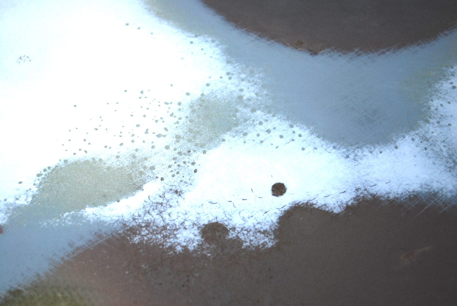
If you look close at this picture, you can see little circles created by the white paint that did not adhere to the primer, and filler. This is what was causing the bubbling over the entire fuselage. But wait!, there's more!


I was really curious now to see the repair on the fuselage, and as I expected, it was not looking too good.
Robert Mudd still hasn't seen this work yet, and what we need to do to correct the repair, if necessary.

I continued to sand away the paint and shaking my head with amazement on how much filler material has been applied on the aft end of this glider!
That explains why the weights and balance for this glider was way off and required the lead weight in the nose.
I had to stop here, I was getting depressed.

I decided to start on the vertical stabilizer, what else could I find here?
The sanding went well. I started sanding with the orbital sander, and when I could barely see the glass peek through, I switched to 180 grit wet-dry sand paper and finished removing the gelcoat by hand.


Then, I hit more of that micro-bubble filler. There were two holes cut just below the horizontal stabilizer notch. It looks like the push rods in the tail could have been serviced, but it was not documented in the airframe log.
After whatever work was done, both sides of the tail were repaired incorrectly, leaving a large depression that was heavily filled with that micro-bubble filler. ..... there must have been a sale on micro bubble when this glider was being worked on!

The left side was the worse. Robert instructed me to remove all of the filler, since that was the material that was causing all of the cracking of the paint to begin with.
With two large dimples in the sides of the tail, these once-filled indentations will need to be cut out and properly repaired.
This will not be the last time I'll see that micro-bubble filler.

Before I can start sanding the bottom of the fuselage, I needed to remove the landing gear doors. These were a problem to remove, there were also indication that the doors were repaired after a gear-up landing, and I'm not too surprised, this repair was not mentioned in the log book. (The gear door repair and clean up to be addressed in a later post.)
The doors were held in place with screws and brass hinges. I had to scrape the paint and bondo off the doors and remove the screws. The screws were corroded and will need to be replaced. The holes will need to be filled and retapped when we are ready to reattach them.

To remove the hinges from the fuselage, they needed to be cut out.

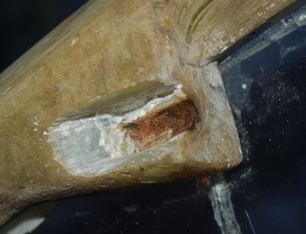
As you can see from this closeup, the rust had creeped into the slot and was deep into the fiberglass.


 By mid November, the temperature outside was hovering around the low sixties, and the weekends were my only time to work on the fuselage.
I finally removed most of the gelcoat before the temperature outside drop below 50 degrees during the day.

Wow!, I can't believe it's almost done! .. the fuselage, that is!
The garage is now starting to get cold, and the work outside has come to a halt.
This will not be the last time I'll see that micro-bubble filler.

Before I can start sanding the bottom of the fuselage, I needed to remove the landing gear doors. These were a problem to remove, there were also indication that the doors were repaired after a gear-up landing, and I'm not too surprised, this repair was not mentioned in the log book. (The gear door repair and clean up to be addressed in a later post.)
The doors were held in place with screws and brass hinges. I had to scrape the paint and bondo off the doors and remove the screws. The screws were corroded and will need to be replaced. The holes will need to be filled and retapped when we are ready to reattach them.

To remove the hinges from the fuselage, they needed to be cut out.

As you can see from this closeup, the rust had creeped into the slot and was deep into the fiberglass.

As I mentioned earlier, I started sanding off the gelcoat on the nose, and after removing a ton of filler, this oily-looking crap started to seep out of the pores in the resin.

It looks like tar .. from the runway???
I used acetone to see if I could clean it out, .....

... but there seems to be no end to it!!
Robert said he wanted to look at it before we go any further with the restoration here.
It looks like they applied the fiberglass fabric over the original finish without cleaning it off!
Robert said he wanted to look at it before we go any further with the restoration here.
It looks like they applied the fiberglass fabric over the original finish without cleaning it off!

I finally removed most of the gelcoat before the temperature outside drop below 50 degrees during the day.

Wow!, I can't believe it's almost done! .. the fuselage, that is!
The garage is now starting to get cold, and the work outside has come to a halt.
By no means is the sanding work finished! I have the wings, ailerons, horizontal stabilizer, elevators, and rudder left to do!
Stay turned for more of the boring saga "Remove that gelcoat!"