Welcome to a work in progress

This blog is dedicated to the restoration and modification of a Glasflügel Standard Libelle H201B, and a tribute to those who have dared to do the same, and to those who are helping with seeing this dream take flight.

Saturday, March 17, 2012

Two years into this project!

Two year to the day that I have been engrossed and obsessed with my unfinished glider. Where has the time gone?

What was done over the second year of work?

The gelcoat was finally removed completely, and the trailer was torn down, sand blasted, repainted, and dropped off to the trailer shop to have the floor boards replaced, re-skinned and a full clam shell lower frame and hinge fabricated. But the cost to do this was higher than the original estimate, and the trailer spent most of the year sitting at their shop until I could afford to pay for the balance of the work that was done, and what is still needed to complete the clam shell lower frame.

I need to mention that a project like this is like all hobbies, it requires money to feed it. I have been on a limited budget that has hindered my ability to move forward at an accelerated pace.
Like last year, we had an early hard cold winter that slowed my progress. But during the winter, I was able to finish painting the cockpit, bulkheads, and seat (to be covered in a future post). I was also able to finish the spar dollies and one mid-wing support (to be covered in a future post).

With tax time around the corner, and hopefully a decent return, I can complete much of the more costly additions, (the radio and O2 system).


 Here is a photo of the parts installed in the cockpit today, and a test fit of the fabric pads.


In the months to come, the plan is to complete the installation of the internal components and deliver the glider to Roberts shop to finish the surface cleanup and finally get some paint back on her,

Thank you for those who have been following this blog.

Friday, March 9, 2012

On the rails!

Part of the fuselage repairs included the rebuild of the canopy track rails that run along side of the cockpit top frame sill.

My Libelle's tracks were chipped and worn down. I was concerned on finding a workable method to achieve the look of the originals.

I decided to try a test on one side, and not completely down the sill.

I used the aluminum duct tape and burnished the tape along the sill and up the edge of the remaining rail. The tape, when handled carefully, makes a straight, flat edge for the resin paste to sit on.

Next, I rotated the fuselage on it's side so the epoxy resin would stay along the old rail edge

Using epoxy mixed with my favorite material (cotton flock), I troweled in the mixture, carefully along the side of the old rail, and feathered the edge into the tape.  


After the resin cured, and I removed the tape, and I found that this method would work.

I was ready to do a full side.


The setup for the right side of the fuselage cockpit sill was the same as I did with the test side.

Next, I used the same mixture and troweled it down the full side.


When the resin cured, I removed the tape and started the clean up with a heavy grit sand paper.

To ensure that I removed the correct amount of waste, I measured the depth of the groove in the canopy frame and made a depth gauge.

I then used a finer grade of sand paper to even out the new rail to the correct shape and height. The gauge verified the correct height of the rail.

The new rail will need some light filling, but for the most part, they are finished!


The sill needs some additional cleanup before the final paint job.

It's time to start putting eveything back into this bird!

Wednesday, February 15, 2012

Creating a new fuselage access hatch - Part 2

Here is an update on the hatshelf hatch cover.

Before the cover is painted and mounted in the fuselage, I needed to decide where and what to do with the radio speaker.

The radio I plan to buy has a radio speaker box, but the size could have created an access problem near the batteries and with push rod articulation.

Robert suggested a speaker for the radio and it looks like it would fit in the hatch.

With a little modification to the outside of the speaker-box, I was able to create mounting point on the case face.

I created a pattern of the grill cover and the screw holes.

I was able to cut the openings cleanly with a Dremel tool and drill.


I then did a test fit with speaker housing.


After a final light sanding on the surface, I applied a primer coat, ready for the next steps, Mounting the piano hinge and painting.


What fun, what joy......

Tuesday, February 14, 2012

Prep'n the cockpit - Fill'n gaps and Painting


It has been an interesting journey to get this far in the project.

The left side of the cockpit showed some stress ware in the glass where the airbrake handle was. I sanded down the inside and prepped the surface to lay in a couple of plys of  E-120 fiberglass.

 After the glass was applied to the inside, I covered the glass with peel ply, and squeegeed the excess resin off.


The seat belt loops were uneven and full of deep grooves. 

After filling the grooves with a flock thickened resin, they were sanded smooth. A coating of primer was used to finish them off. I also primed the area around the loops that were visible though the seat pan.  
The areas that were not intended to be painted were masked off with painters tape.

The sides were then primed, sanded and prepped again.


 The floor of the nose was primed and sanded smooth.  


The final priming and finishing of the cockpit prior to painting.


Right side


Then nose interior primed.


The cockpit was painted with DCC semi-gloss light grey paint.
The finish is more glossy than satin.


I dropped in the seatpan to see if the masked areas were visible.


The last part to be painted was the nose bulkhead for the Pitot pot.


Time is getting closer to start reassembing the glider.

Tick Tock, Tick Tock!


Friday, January 27, 2012

Humpty Dumpty ( I hope not! ) - Part 1, The Re-Plumb

After two years of ups and downs on this project, it's time to put her back together!

The parts were all checked, clean, and their new hardware were tested and installed prior to their final placement in the fuselage.

I can't wait to get this room back.

The cockpit is painted and the first "to do" is replumbing the pneumatics.


I have purchased new PVC tubing, nickle plated metal connectors and a replacement 5-way Quick Connector from Cumulus Soaring. I also bought replacement semi-rigid polyethylene tubing for the runs through the cockpit sides.

Before replumbing the glider, I needed to get the tow release installed and the nose bulkhead resealed and secured, and mount the ground wires.

I first made the ground wires. The wire ends were crimped, soldered and sealed with heat shrink tubing.


There were two ground wires made. One for the rudder pedal adjustment rail, and one of the tow release.


The ground wires were taped to the floor of the glider, and then a few strips of fiberglass fabric were applied and sealed with resin.


The forward wire was a simple straight shot to where the foot pedal adjustment rail.


The wire needed for the tow release had a curve in it to keep it clear of the cable release arm. 


The wire was also taped down to hold it in place, while a mix of chopped glass and fabric, wet with resin was, was applied.


After the resin cured, the wire was test fitted to the pole use for the cable release arm.


The next step, was to mount the brake cable housing.

Since the cable housing is fairly rigid and springy, I needed to weigh the housing down, when I was applying the fiberglass.

I followed the original groove, left behind by the old break cable housing.


A layer of peel ply blended the edges of the glass while the resin cured.


Weights and peel ply removed.


The original opening into the wheel well was a jagged opening that the cable sawed across. I sealed the opening and the drilled a new opening that a rubber grommet could fit in.

I slid the brake cable housing through the grommet.
Neat and clean.


The grommet and cable from inside the painted wheel well.


It's time to install the tow release and the nose bulked. I installed the steel cable on the tow release, and using Tim Mara's advice to install the tow release, I rotated the fuselage inverted, which made it easier to reach the mounting plate.


I attached the tow release and fed the cable into the plastic rigid tubing.


The nose bulkhead was a bit tricky. I found the tape putty used to seal windows. This was the same type used in the original seal years back.

I softened the sealant, and spread it on the lip of the bulkhead, like it was originally. then I reattached the bolts and tightened them evenly around the frame so the sealant would spread out. After the bulked was tightened down, any excess sealant was removed. I then used a little alcohol to clean up the area. To test the seal, I attached a shop-vac to the tow hook release opening and with the vacuum set to blow, I was able to pressurize the nose chamber to detect any leaks around the seal.


I installed the rudder pedals and fed the steel cable through the original rigid tubing.
Using the pull string I ran through the tail boom for the COAX run, I was able to pull a replacement RG-58 COAX for the antenna. It was the easiest part of the project so far!


The transponder uses RG-400 and is a little stiffer, but it pulled well into the area aft of the wheel well.

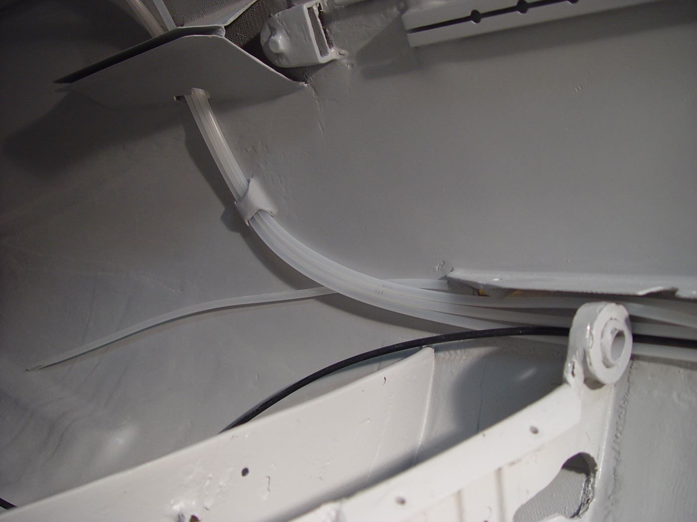
I then pulled the pre-measured runs of semi-rigid polyethylene tubing to complete the pneumatics in the cockpit sides.

The vinyl tubing from Winter was cut and attached to the rigid tube segments. I used tube clamps to secure them. I hope never to see a tube separate like the ones I found when I first inspected this glider.

I attached the capacity flask using the same technique.

And finally, I connected the pitot, TE, Flask, and static tubes to a 5-way connector, and color coded them.


Here is a before and after shot of the forward cockpit.


Next,  .... let's do some wiring ....

Wednesday, January 25, 2012

Test fit

Over the summer (between the rain drops), I was getting antsy on getting further along on my project, I had to see my bird in a shape different than the way she has been sitting for the past two years.

I strapped the fuselage on a cart, and rolled her out into the driveway.


Attached a wing, and mounted a fairing, just to see what they look like.

 
This also helped me measure the length of the wing root for the new tailer cap.


And also to see how much of the fairing covers the canopy frame.


Soon to be a reality!


Making new GRP Holders and Straps

Pass me a bottle... please!
Now that all of the gelcoat has been stripped off of the glider, my focus has been to get the interior of the cockpit finish, so we don't damage the outside before we are ready to prep it for painting.

For those who are just joining in, over a year ago, when I started this project, I found an old thermos bottle rolling around in the fuselage.


Being new at this, I was unfamiliar with use of a capacity flask, and back in the day, thermos bottles were used as one.

Several months later, I purchased a new Winter Vario to replace the thirty-plus year old one. The new Vario came with a new light weight .9 liter flask.


I'm now working on creating those fiddlie bits to secure parts in place.

I had a discussion with Robert on how some components are secured in the glider, in this case, mounting this flask, and where.
He stated, you will need to make a cradle out of fiberglass for the flask. As for the location of the bottle, it is recommended that the placement of the bottle needs to be equidistant from the TE probe to the Vario. This placement is close to where the old Thermos was located.

And here is where the old Thermos was glued. It was against the outside of the wheel well and resting on the right side of the belly.

Another area that will need to be cleaned up before I can move on.


To start with making the Capacity flask holder, I needed to make a mold of the flask ends so I could create a cup to keep the flask from sliding back and forth in the holder.

Using the flask as a male form, I molded aluminum foil around the end. I smoothed the foil out the best i could do to create a female mold. I then pored urethane resin into the temporary mold. After the resin hardened, I removed the foil. After repeated coats of filler, I had a smooth finish. I used a polyurethane paint to finish the surface.

The last step was to lay over a couple of plys of 7725 glass with epoxy resin to create the cups.

To create the cradle, I wrapped a piece of plastic around the flask to create a tube shape.


I then layed a couple of plys of fiberglass to create a half-tube.
After the resin cured, I cut two pieces to the length needed for the cradle.


I cleaned up the end caps with the cradle parts, and test mated the parts to ensure that they were even.


I needed to replace some of the original GRP straps used as tubing and wire restraints, and this shape can also be used make a stand-off for the bottle cradle.


I made a mold for the bottle stand and straps using a piece of hard wood, seal and waxed it well to keep the resin from sticking to it.


I applied three layers of 6 ounce fiberglass .


After the resin cured, the sheet form popped off without any problems.

The finished stand-off rail sheet.


I trimmed away the excess glass on the sides, leaving a lip on the stand-off for the flask cradle to rest on, and an adhesion area for the epoxy resin.

I tested the shape of the flask cradle to make sure that the form was level, and then did a final trimming before applying the epoxy resin cement.


The end caps were cemented to the cradle form with a light amount of epoxy resin.


When the epoxy cured. I carefully cleaned of the shape by sanding the off the excess resin, and then evened the sides of the shape.


A reinforcement fiberglass strip was added to the both the inside outside of the flask holder ends.


After the strips had cured, I trimmed off the excess.


And lastly, the trimmed standoff was epoxied into place and a strip of 6 oz glass was applied to the sides to reinforce the shape.


In the bottom of the cradles stand-offs, I cut openings for plastic zip-ties to secure the flask when it is installed in the fuselage.


The flask holders where finally cemented in fuselage. Additional strips of fiberglass, wetted with resin, secured the stand-offs on the clean fuselage skin.


How the finished flask holder looks in the belly.


The next task is to replace the old lost and dried out straps for the hoses and wiring.
I needed to replace four straps, three in the nose, and one in the side.

Using the same mold, I created a sheet glass of the pre-shaped form for the replacement straps


New straps were cut to the same size as the original, and using a thickened epoxy, I glued the straps in while having the fuselage rotated upside-down.

Masking tape held the straps in place while the resin cured.


The tape was removed and any excess resin was sanded off and the straps smoothed to hold the pitot hose.


The side strap for the wiring was secured using the same technique as straps in the nose.


I sanded and painted the area around the strap.


For the water dump system, there is a Teleflex cable used to active the valve. I created a GRP strap to hold the cable in place. To create the straps, I used a wood dowl rod that was the same diameter of the cable. I cemented the rod to a board, and filled the sides to level it to perpendicular to the board.


I used two plys of fine fiberglass bonded with epoxy resin.


I added peel ply to smooth the surface.


After the resin cured, I removed the sheet and trimmed away one side.


I cut several tabs to be cemented in the cockpit side.


Following the drawings for the water dump system used to convert the H201 the 201B, a resin paste was used to attached a few of the tabs which will be used to secure the Teleflex cable.


After the resin cured, I cleaned up the tabs and slightly painted the area with primer.


The cable I have is a throttle cable, and not an official Telefex cable. I could not find a cable the correct length. My glider did not have a cable. So, this find was perfect, the only problem was, there was no way to mount it to the rear cockpit bulkhead. I made a mount that will be used as stand-off for the end which is used to attach it to the valve lever.


The stand-off was made of a mix of epoxy resin and flocking. A stainless steel bolt molded into the form.


I sanded a grove in the top of the stand-off for the cable ferrel to rest in.

I will use resin and fiberglass strips to secure the cable to the stand-off. I will install the valve actuation cable after I receive the proper water ballast system kit from Streifeneder.


Time to do the final sanding in the cockpit before painting.