After two years of ups and downs on this project, it's time to put her back together!
The parts were all checked, clean, and their new hardware were tested and installed prior to their final placement in the fuselage.

I can't wait to get this room back.
The cockpit is painted and the first "to do" is replumbing the pneumatics.
I have purchased new PVC tubing, nickle plated metal connectors and a replacement 5-way Quick Connector from Cumulus Soaring. I also bought replacement semi-rigid polyethylene tubing for the runs through the cockpit sides.
Before replumbing the glider, I needed to get the tow release installed and the nose bulkhead resealed and secured, and mount the ground wires.

I first made the ground wires. The wire ends were crimped, soldered and sealed with heat shrink tubing.

There were two ground wires made. One for the rudder pedal adjustment rail, and one of the tow release.

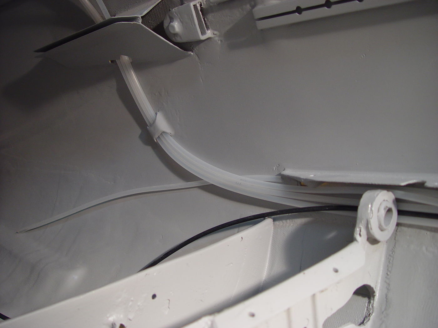
The ground wires were taped to the floor of the glider, and then a few strips of fiberglass fabric were applied and sealed with resin.

The forward wire was a simple straight shot to where the foot pedal adjustment rail.

The wire needed for the tow release had a curve in it to keep it clear of the cable release arm.


After the resin cured, the wire was test fitted to the pole use for the cable release arm.

Since the cable housing is fairly rigid and springy, I needed to weigh the housing down, when I was applying the fiberglass.
I followed the original groove, left behind by the old break cable housing.

A layer of peel ply blended the edges of the glass while the resin cured.
 Weights and peel ply removed.
The original opening into the wheel well was a jagged opening that the cable sawed across. I sealed the opening and the drilled a new opening that a rubber grommet could fit in.
I slid the brake cable housing through the grommet.
Neat and clean.

The grommet and cable from inside the painted wheel well.

It's time to install the tow release and the nose bulked. I installed the steel cable on the tow release, and using Tim Mara's advice to install the tow release, I rotated the fuselage inverted, which made it easier to reach the mounting plate.
I attached the tow release and fed the cable into the plastic rigid tubing.

The nose bulkhead was a bit tricky. I found the tape putty used to seal windows. This was the same type used in the original seal years back.
I softened the sealant, and spread it on the lip of the bulkhead, like it was originally. then I reattached the bolts and tightened them evenly around the frame so the sealant would spread out. After the bulked was tightened down, any excess sealant was removed. I then used a little alcohol to clean up the area. To test the seal, I attached a shop-vac to the tow hook release opening and with the vacuum set to blow, I was able to pressurize the nose chamber to detect any leaks around the seal.

I installed the rudder pedals and fed the steel cable through the original rigid tubing.

The transponder uses RG-400 and is a little stiffer, but it pulled well into the area aft of the wheel well.


Here is a before and after shot of the forward cockpit.


Next, .... let's do some wiring ....
Hi John, Great Blog! I just purchased a Standard Libelle H201. I have a fitting in the nose bulkhead for a pitot hookup that extends about two inches fore and aft of the bulkhead. What does your plumbing do in front of the bulkhead? Does it continue out of the opening for the tow release?
ReplyDeleteThanks, Gary
Hello Gary... It sounds like mine. The pitot opening is just stubbed into the pressure pot opening. I have made about 14 flights and the ASI seems to be working just fine with the original design. On tow, it might be off, but I'm just concentrating staying behind the tow plane and did not notice what the ASI was reading. If I'm still flying while on tow, the airspeed is good! ;)
Delete